
A presentation from the World Oil Shale Tech Conference dives into what makes the jet pump artificial lift system a flexible and lower cost means of unloading wells.
Abstract
A step forward in development of a novel Hydraulic Jet Pump yields an efficient, flexible and lower cost means of unloading wells, especially horizontal multi-stage fractured wells such as in unconventional resource development.
The new system is available in a model that allows full access through the pump housing and into the horizontal wellbore with the pump and check valve removed.
As the Jet Pump has NO moving parts, sand laden fluids and placement of the pump in the horizontal section for greater drawdown are additional advantages provided by this artificial lift system to enhance recovery rate as well as reduce maintenance costs.
Repair or re-design of the pump due to changes in the well production capacity can be achieved without the use of a workover rig. The pump is retrieved by reverse circulation, repaired or production capacity design changes made to optimize horsepower requirements. The pump is then circulated back into the well to seat in the pump housing and the well returned to production.
Improved efficiency and quality have been achieved through the application of new manufacturing technology to eliminate welding of any of the components, improve flow capacity, improve efficiency and enhance pump life with special coating processes.
Hydraulic Jet Pump Operations
A Jet Pump operates on the Bernoulli Principle where, as the velocity of a moving fluid increases the pressure in the fluid decreases and vice versa. This same principle is used in many other common apparatus such as the airplane wing, atomizers, aspirators, etc.
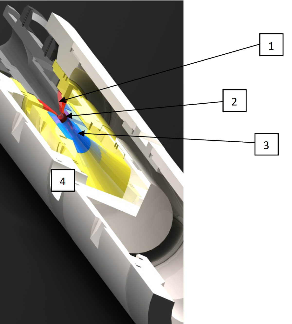
As shown in Figure 1, power fluid is pumped through a small orifice or nozzle (1) where the fluid achieves high velocity and low pressure at the outlet of the nozzle. This low pressure area (2) creates drawdown to allow entrance of production fluids into the flow stream. Below the nozzle is a mixing tube (3) with progressively larger flow area creating lower velocity and subsequent higher pressure to return the fluid mixture to the surface (4).
Many pumps are designed to allow retrieval of the carrier (containing the nozzle and mixing tube) by reverse circulation thereby eliminating the need for a workover rig to repair or redesign the pump for changes in well conditions.
The most common pump installation uses the tubing as the conduit for power fluid with power fluid and production mix returning up the annulus between the tubing and casing.
Another configuration is available whereby power fluid is pumped down the annulus with the production fluid mix returning up the tubing. This configuration can be coupled with a surface pressure controlled, fail safe, safety valve for use in offshore installations or where a SCSSV is required or desired.
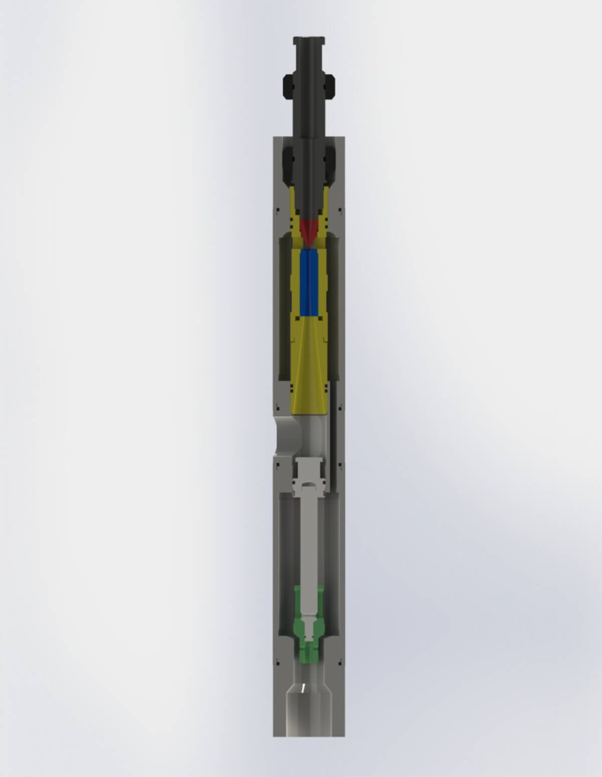
In wells where the production rate is low as in unloading a gas well or in older or corrosive flow stream wells where it is not desirable to have the produced fluids in contact with the casing ID, a dual tubing string configuration is utilized as shown in Figure 2.
With NO moving parts in the pump, the Jet Pump is tolerant of high solids content flow streams and functions reliably in any position, including many actual installations in the build section or horizontal section of wellbores.
Figure 2 depicts a new pump design which allows retrieval of the pump and standing valve using reverse circulation and/or wireline to provide full access to the producing formations below the pump for cleanout, pressure measurement, or other remedial operations.
The through bore concept is also available in several models where the pump is positioned across a Sliding Side Door with the entire pump retrievable by wireline, the SSD closed and integrity of the tubing string restored for the natural flow phase of the well production. The disadvantage to this system is that the entire pump assembly is smaller and therefore not capable of the high rates of the 3.1” OD new pump design.
Standard Unloading and Production Operations
For use as an artificial lift system in hydraulically fractured wells, the following is a simplified step by step procedure of the more popular method of unloading and producing the well.
- Install the pump Housing in the tubing string during completion. Housing is fitted with a blanking sleeve (optional) to eliminate well pressures from casing/tubing annulus and provide pressure integrity of the tubing for operations such as packer setting, integrity testing or plug expulsion/retrieval.
- Flow well back until production rate declines
- Retrieve the blanking sleeve by reverse circulation (if installed)
- Insert Jet Pump carrier and pump down to seat in Housing
- Unload and produce the well using the Jet Pump as an artificial left method until well begins natural flow. High horsepower surface power units are generally rented for this short time period of a few weeks.
- Reverse the pump out of the well and pump the blanking sleeve down to seal across the outlet port in the pump housing (optional)
- Flow well until production rate declines to an unacceptable level
- Retrieve the blanking sleeve (if installed) and re-install the Jet Pump. Surface power units can be properly sized to minimize horsepower as productivity data should be readily available following the natural flow period of the production cycle.
- Produce the well on artificial left using the Jet Pump.
This system also provides multiple features that enhance the safety of operations such as loss of pressure integrity at the stuffing box or power cable pack off if adjacent well fracturing treatments communicate with the producing well creating high surface pressure.
In multiple well pad operations, a 175 HHP surface unit can be utilized for unloading each well individually at rates in excess of 2,500 BPD. Once natural flow ceases and artificial lift is required, the 175 HHP pump can serve as power fluid pump for up to 4 wells at rates in the 300 to 400 BPD range.
Where a 4 1/2” frac string is run from surface to the liner top, the Jet pump can be run on 2 3/8” or 2 7/8” tubing inside the frac string with a packer including a rupture disc set inside the liner top. The Frac string is then stripped out, leaving the production tubing in place and with complete well integrity during the Frac string removal. Pressure testing of the tubing and casing can be achieved as well as expulsion of the rupture disc allowing the natural flow back phase with production up the tubing. Steps 3 and 4 above then places the well on artificial lift flow back until natural flow of hydrocarbons is achieved.
Artificial Lift Surface Power Unit
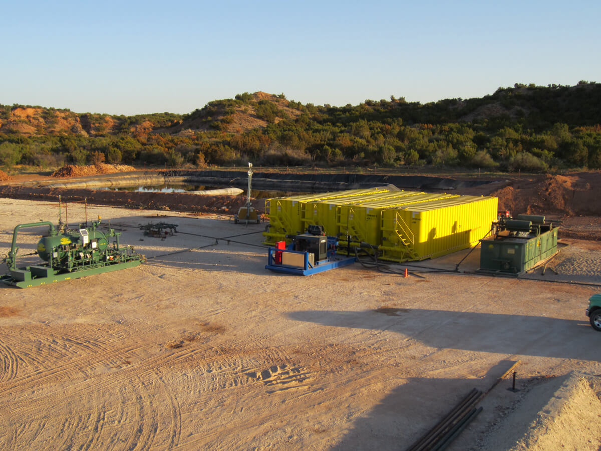
Figure 3 a surface power unit is available, either electric, diesel or including a natural gas prime mover with controls that allow fail-safe operations and utilizes “dirty” gas with BTU levels from 800 to 2,250. Using normally flared gas provides an additional economic benefit to the overall operation.

Hydraulic Lift Case Studies
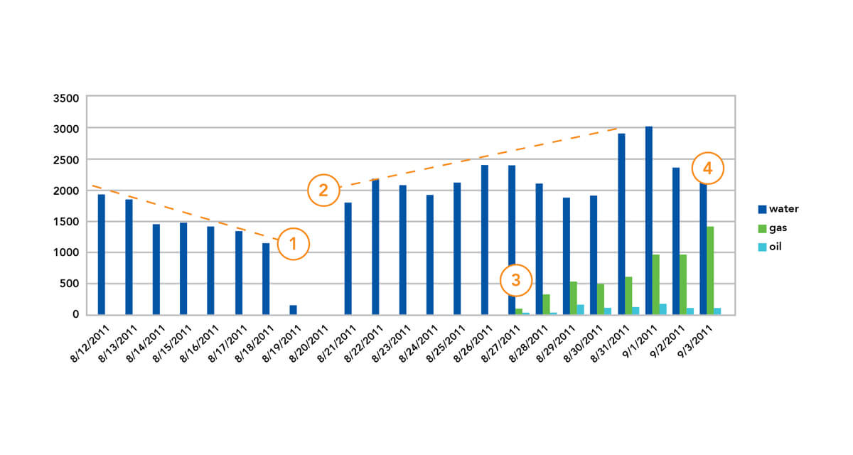
A typical unloading and producing sequence is shown in the chart of Figure 4 where section 1 is natural flow with initial flow back at rates near 2,000 BPD and decline to no flow in 8 days.
Section 2 of the chart is the period of artificial lift using a jet pump with production rates controlled at 2,400 BPD for a period of 7 days prior to the first produced oil and gas.
In 14 days of total production time (natural flow and pumping with the jet pump), 32,000 bbls of frac fluid were recovered with hydrocarbon production seen only 16 days after the fracturing treatment (Section 3).
Section 4 shows the initial days of natural flow after the unloading process and termination of jet pump operations.
Examples 1 thru 4 provide production rates and power consumption for producing wells converted to jet pump from various other artificial left methods.
Example 1
Average production:
Beam pump, 260 BWPD, 20 BOPD, 75 HP pump
Jet pump, 400 BWPD, 28 BOPD, 70 HP
Oil production increased 8 BPD with less HP
Elimination of prior year beam pump repairs in excess of $130,000.00
Payout 2.6 months including repair cost reduction
Example 2
Average production:
ESP, 500 BWPD, 10 BOPD, 180 HP
Jet pump 550 BWPD, 15 BOPD, 27 MCFD, 150 HP
No maintenance required in first 18 months
Corrosion inhibitor chemicals are continuously injected into the power fluid
Payout 5.1 months including NO repair costs
Example 3
Average production:
Gas lift, 333 BWPD, 22 BOPD, 80 HP
Jet pump, 522 BWPD, 35 BOPD, 161 MCFD, 70 HP
Lease required purchase of make-up gas to supply the gas lift system
Actual gas sales were initiated after installation of the jet pump.
Payout 2.7 months
Example 4
Average production:
Plunger Lift, 54 BWPD, 120 MCFD
Jet Pump dewatering installation, 68 BWPD, 285 MCFD
Operation achieved with a 25 HHP surface pump
Payout 4.2 months